The free atmolight system was designed to drive 4 channels with ether LED strips or coloured cold cathode tubes. They are using a specially designed controller board which has the microcontroller, all the power and the PWM stuff on it.
So all the lights are connected to this one board and one serial or usb connection will go to the pc which will provide the data.
the idea is not so bad and it is actually not too expensive, but you need to get the board, all the other parts, solder everything, program the microcontroller and then you are good to go. (if it works)
too much work for my taste, but will come to this again later ...
The serial Protocol - Now it gets interessting ...
Until now i'm just using the main colour value data, which is streamed over the serial port.
When you are using the AtmoWin App or the atmolight module in videolan, the standard packet layout will by like this.
0 | 0xFF: Startbyte |
| 1 | 0x00: Startchannel (low byte) |
| 2 | 0x00: Startchannel (high byte) |
| 3 | 0x0F: how much channels (15 = 5 * 3 (R, G, B)) = what if have seen, it's always 0x0F |
| 4 - 6 | sum channel R, G, B (Center) |
| 7 - 9 | left channel R, G, B (Left) |
| 10 - 12 | right channel R, G, B (Right) |
| 13 - 15 | top channel R, G, B (Top) |
| 16 - 18 | bottom channel R, G, B (Bottom) |
for example:
0xff 00 00 0f aa aa 11 aa aa 11 aa aa 11 aa aa 11 aa aa 11 (all channels will have the values R=170,G=170,B=17)
There is a control command to adjust the brightness, contrast, gamma, gamma for each channel and the whitebalance directly within the mikrocontroller code.
Whitebalance adjust command
Byte Beschreibung
0 0xFF: Startbyte
1 0x00: Startchannel (low byte)
2 0x00: Startchannel (high byte)
3 101: Triggerbyte / commandbyte for WB adjust
4 brightness
5 - 7 contrast R, G, B
8 - 10 gamma R, G, B
11 global contrast
12 write command / write to eeprom
note: each colour change will be a full packet ... when you are using the AtmoWin app in fixed color mode, it will send the packet only at startup or a mode change
also note: videolan and atmowin allows to change the order of the channels, just try to remembder it ... i did a hardcoded channel order in my code, to assign the channels to the different led bars. ... needed to do this, because i currently have two led bars for each of the three channels i'm using
Light Value transformation
The atmolight guys using a gamma table to transform the linear rgb light values to values used by the PWM output modules. It just looks so much better with this on.
I can't really explain why, but someone will know. ... :P ... i just implemented what they did
a very good explanation by Garrett from macetech ...
"The gamma table fixes the problem human eyes have correctly determining brightness of pulsed light. Even though PWM from 0 to 100% duty cycle is accurately changing brightness in a linear way, the eye sees almost no difference between 75% and 100% brightness. So the gamma table uses something like a logarithmic translation; the values will change very slowly at low brightness and very quickly at high brightness."

this is the table they are using ... 255 Values over a range of 0 - 2047
0;0;0;0;0;0;0;0;0;0;1;1;1;1;1;2;2;2;3;3;4;4;4;5;6;6;7;7;8;9;10;11;11;12;13;14;15;16;18;19;20;
21;23;24;25;27;28;30;31;33;35;37;38;40;42;44;46;48;51;53;55;57;60;62;65;67;70;72;75;78;
81;84;87;90;93;96;99;103;106;109;113;116;120;124;127;131;135;139;143;147;151;156;160;
164;169;173;178;183;187;192;197;202;207;212;217;223;228;233;239;245;250;256;262;268;
274;280;286;292;298;305;311;317;324;331;338;344;351;358;365;373;380;387;395;402;410;
417;425;433;441;449;457;465;474;482;491;499;508;516;525;534;543;552;562;571;580;590;
599;609;619;628;638;648;658;669;679;689;700;710;721;732;743;754;765;776;787;799;810;
822;833;845;857;869;881;893;905;918;930;943;955;968;981;994;1007;1020;1033;1047;
1060;1074;1088;1101;1115;1129;1143;1157;1172;1186;1201;1215;1230;1245;1260;1275;
1290;1305;1321;1336;1352;1367;1383;1399;1415;1431;1448;1464;1480;1497;1514;1530;
1547;1564;1582;1599;1616;1634;1651;1669;1687;1705;1723;1741;1759;1778;1796;1815;
1833;1852;1871;1890;1909;1929;1948;1968;1987;2007;2027;2047
the newer original firmware generates the table on startup, will look at this later and add it to my arduino code ...
The gamma table fixes the problem human eyes have correctly determining brightness of pulsed light. Even though PWM from 0 to 100% duty cycle is accurately changing brightness in a linear way, the eye sees almost no difference between 75% and 100% brightness. So the gamma table uses something like a logarithmic translation; the values will change very slowly at low brightness and very quickly at high brightness.
ReplyDeletethx ... ;)
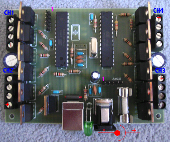
ReplyDeleteIf you want to build your own 'original' Atmolight (exactly as seen in the above picture), you can order the PCB (even including pre-programmed µControllers) at my Website
ReplyDeletehttp://ca.rstenpresser.de/~cpresser/atmo.html
http://ca.rstenpresser.de/~cpresser/atmofaq.html
The plain PCB is availabe for 8Euros + Shipping.
I even offer pre-build and tested devices, including LED-Stripes and PSU :)
http://ca.rstenpresser.de/shop.php
Would it be possible to do this with an analog video input (RCA, VGA), or even a digital video input (DVI, HDMI) as opposed to a USB connection from a computer?
ReplyDeleteI have several inputs that I'd like to run this through for my home theater, and my receiver's got a "monitor" or "preview" output that would be perfect for this..
Hi i was just going over your arduino code again and i noticed here in your explanation of all the bytes in the codeframe that you wrote that it will use the 3rd byte in the frame to set the number of channels. When I a look at the arduino code i noticed that the number of channels in the loop for incomingatmo is hardcoded to 5 channels and so it never reads 3rd byte as a channel byte but in stead it will use that 0x15 as the RED value for the SUM channel. Am i seeing this wrong?
ReplyDeleteThis comment has been removed by the author.
ReplyDeletethe orginal atmolight software always sends a 0x15 as the 3rd byte in the frame because the software doesn't allow more channels and you can't configure less ... but because i found a protocol definition which stated that this will give you the size of data to expect i read it out, but don't use it the loop. every software i used, which had the atmolight protocol, did always send 0x15 so i didn't bother to change it.
ReplyDeleteso for the question is RED/SUM is always 0x15,
yes, i'am sorry to say it but you'r wrong ...
because of the way i calculate the byte positions for each channel, the 1st byte [index=0] will be ignored
let me give you a short example ...
the statement with channel=0 and Channelorder for SUM is channel 0 ...
LEDChannels[channel][0]=gammatable[incomingatmo[(channelorder[channel]*3)+1]]; //red
will get the 2nd byte [index=1] in "incomingatmo" ... incomingatmo[(0*3)+1]
I noticed that just now. I didn't look up that far but I see what you are now :-). Thank you!
ReplyDelete